
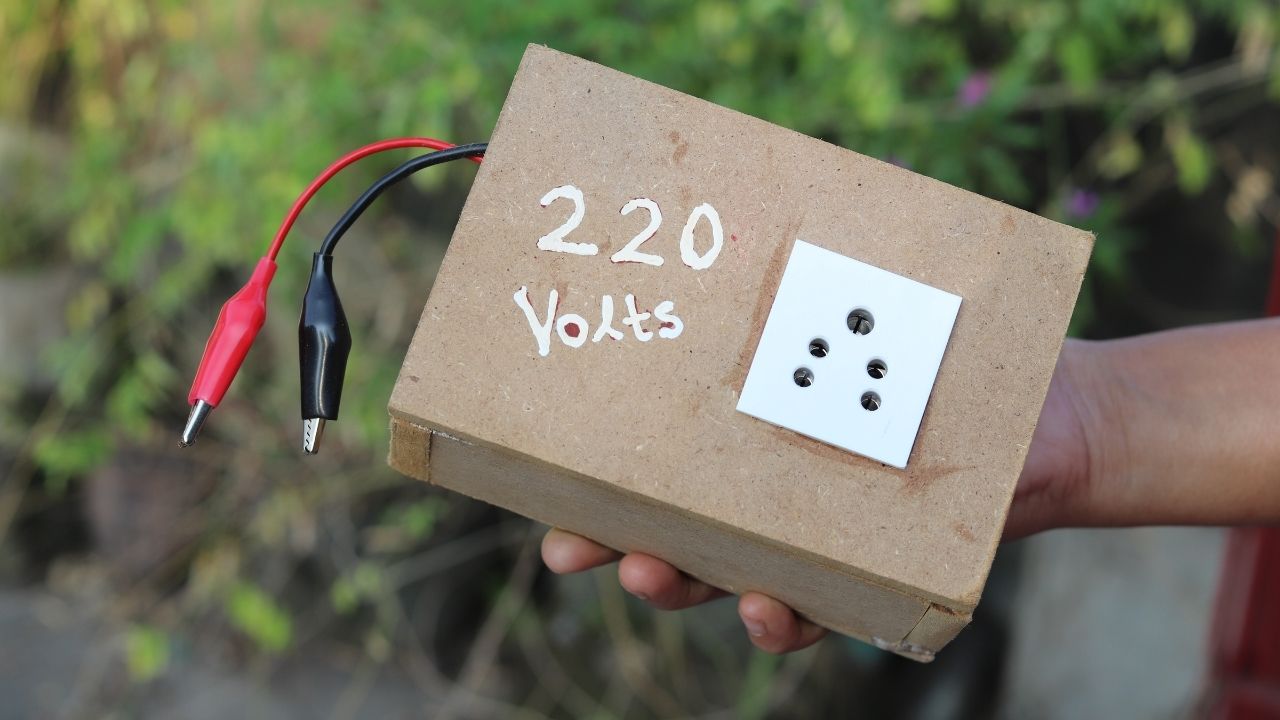
Today in this article we are going to make a 100W Inverter circuit with TL494 PWM IC. The main function of the IC is to create variable PWM Pulses for different applications. Now for making the Inverter we have to make a 50Hz signal ( By calculating PWM Pulses). We will use a couple of other complimentary components for making the Inverter possible. The components are Some Resistors and a capacitor.
If we check the IC Datasheet then we will find some Important equations to calculate the important parameters of the IC. Sometimes it is also not possible to get the exact value of the components. Then our motive will be to find the components which have the nearest value.
Components for the Circuit:
- TL494 IC – 1
- IRFZ44N MOSFET – 2
- 220R Resistor – 2
- 2.2k Resistor – 1
- 4.7uF Capacitor – 1
- 2 Pin Screw Terminal Block – 1
- 3 Pin Screw Terminal Block – 1
- 12v Battery Connector – 2
- 12v Battery – 1
- MDF Sheet (8MM) – 1
- 10MM Wood Screws – 20
- 5 Pin Socket – 1
- 220v to 12v-0-12v Transformer – 1
Tools Required:
- 60W Soldering Iron
- Soldering Iron Fine Tip.
- Soldering Iron Tip Cleaner
- Pliers
- Jigsaw.
- Drill Machine.
- Different Drill Bits.
- Glue Gun
- Flux
- PCB Holder.
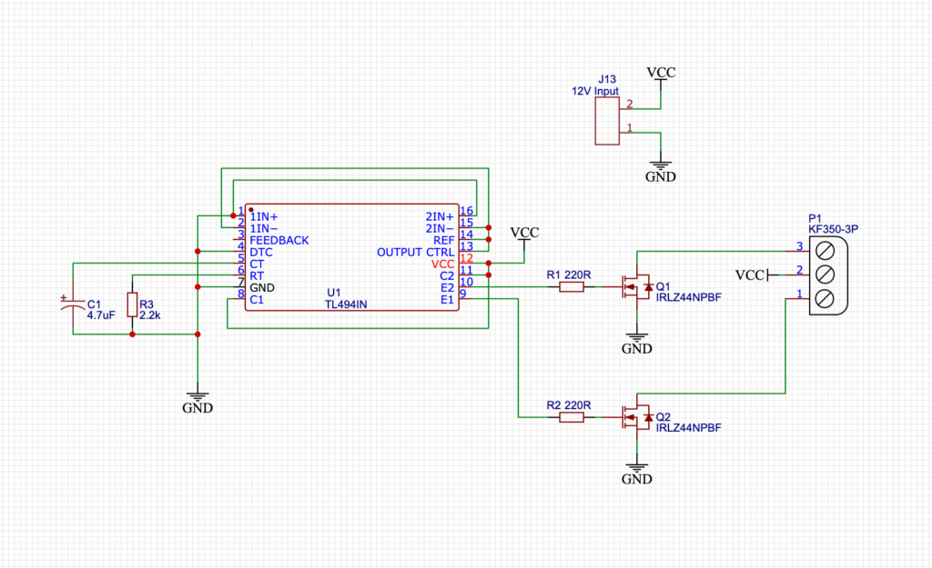
Circuit Diagram:
The P1 terminal block is used for sending the 12V DC Power and The J13 terminal is for giving the 12V Input to the circuit. For the Mosfets, you can use an N-channel MOSFET as your wish. I had the IRFZ44n Mosfet lying around so I used that. You can also use IRF3205 as well.
How does the TL494 Inverter work?
This is the simplified diagram for the 100W Inverter Project. R1 and R2 are the Gate resistors for the MOSFETs. this protects the MOSFET from over-voltage damage. The voltage that is needed to operate the MOSFET will be provided by the Gate resistor. So, The gate resistor is a very important component.
Now for generating the 50Hz signal we only need 2 basic components. One Capacitor couple with a resistor. And the P1 Terminal block is for sending the squire wave pulses to the Transformer Primary coil. Now from the Transformer secondary coil, we will get the 220V Output.
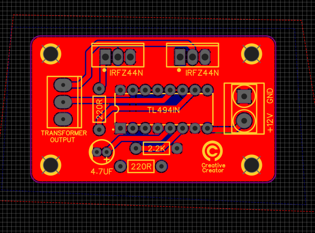
PCB Making:
I made the schematics and the PCB. Then I ordered it from PCB manufacturer JLCPCB. They are professional at their work. PCB looks Promising and can ship to your doorstep within a week. I have to say their customer service is superior. So, I prefer JLCPCB from Other PCB Manufacturers. You can also order PCB from JLCPCB with the following Gerber file.
PCB Layout:
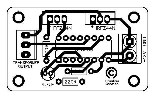
Fabrication File:
PCB Gerber file link