

Introduction:
In this short descriptive article, I am going to discuss how to make an AC voltage detector circuit with intensity control. Here I am using some small components for making this. You can also get these components from old electronics circuit boards. We will need two NPN transistors and one PNP transistor. All connections are so simple that a beginner can also do that. I have also included schematics for better understanding.
How does the AC voltage detector circuit works?
This circuit is based upon simple transistors. We all know the transistor is used for switching and amplification purposes. here we are using the NPN transistors for signal amplification. The two NPN transistors are connected in the Darlington Pair configuration. This type of configuration is often used for signal amplification.
The 2nd NPN Transistor’s amplified signal grounds the PNP Transistor. So it activates the PNP Transistor. And this PNP Transistor Runs the LEDs.
From these two stages, we can get a signal on or off whether there is an AC connection or not. If there is on or off we will direct the signal to a PNP transistor so that this PNP transistor drives two LEDs.
This amplification was done through different stages. Like half stage and full stage. these are connected in such a way that first you will get the voltage first and another one. so when the stage is happening then the first led is getting voltage and the second it is not. so only one led is running. at the first stage, we can see e the PNP transistor is fully active so it runs all the current through the LEDs. So, In this state current flows both the LEDs. so that two LEDs light up.
I have told only two stages in this process for better understanding. but it is not like that it has few more than that. so when you were taking the wire near the AC line then the signal becomes stronger and two LEDs run. and when you take the wire far from the AC line then the two LEDs will off gradually.
Schematics:
This schematic was designed in EasyEDA. I have also marked Emitter, Collector, Base for a better understanding of where to connect which components. Two 22R Resistors are mainly current limiting resistors. You can use any resistor value between 20R to 100R in place of a 22R resistor in case you have not found it.
The Q2 and Q3 are NPN Transistors. Here I used C1815 Transistors. Here any NPN Transistor will work just fine. The Q4 is the PNP Transistor. In this project, I used the BC558 PNP Transistor. You can also use any PNP Transistor as your wish.
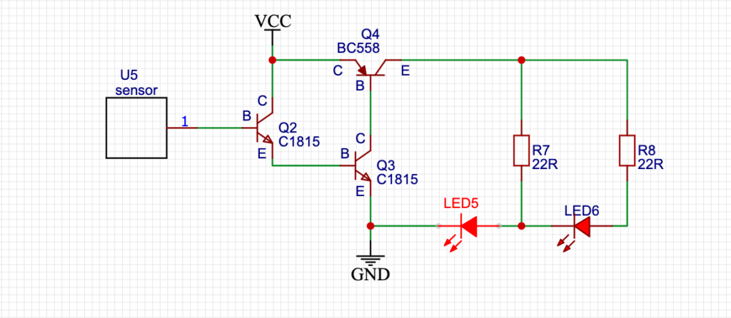
The Q2 Transistor’s Base Pin is used for sensing the Pulses. so we have to connect an external Antena like thing with the transistor’s base. This thing is mainly a capacitor that mainly takes charges and after that, the transistor amplifies the signal.
For the LEDs you can use any. Like 3MM to 10MM any type of LED can be used in this circuit. I have 5MM LEDs laying around so I used 5MM Yellow LEDs.
For the Supply voltage I used 2S 18650 Li-ion Battery. Any voltage of 5V – 9V should be fine for this AC detector circuit with intensity control.
Components Used in this Project:
- 18650 Battery
- 18650 Battery Holder
- LED
- Resistor Set
- Capacitor Set
- 3W LED
- 10MM LED
- Transistor Set
- Heat Shrink Tube
Tools Used:
- Soldering Iron
- Flux
- Solder Stand
- Soldering Paste
- Wire Stripper
- Cutter
PCB File:
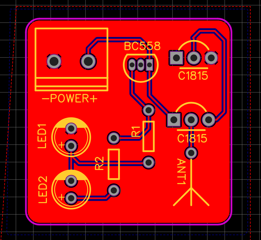
Here is the PCB File in case if you want to make a PCB of the Board.
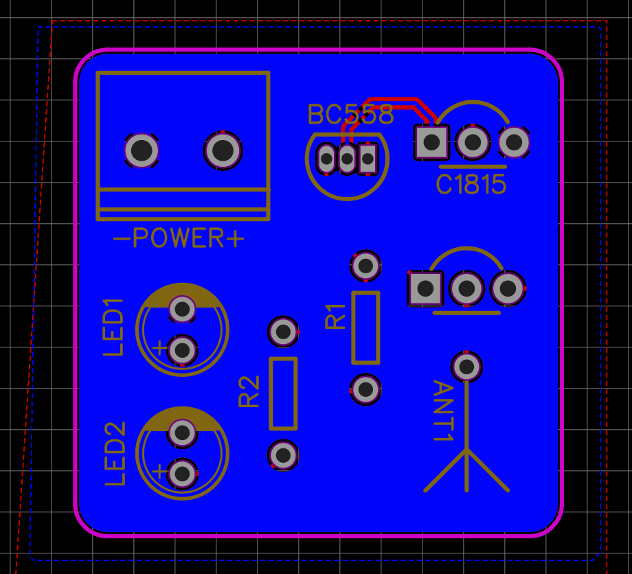
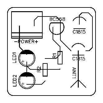
Here is the PCB files for Printout. Which you can print and use it for for Homemade PCB Making. You have to use PCB Aching Process for making the circuit in this way.
PCB Gerber:
Here is the Gerber file which you can send to any PCB Manufacturing company for making a professional PCB for the project.
Watch video:
Here is the video that explains all the necessary connections for making this simple circuit. Make sure you double-check all the connections before making the circuit. Otherwise, you may fry the transistors.
Conclusion:
This project needs a very small handful of components. So, you should definitely try this at your home. Electronics are easy and fun. But be careful while working with high voltages. You can get all the components from your local shop or from old electronics motherboards, DVD players, and much more. If you like this type of small circuit you may definitely subscribe to Creative Creator for more amazing content like this.