

How to make a Variable Dimmer Circuit with ATTiny85 Microcontroller?
Today in this article we are going to make a variable LED Dimmer circuit with a very small microcontroller that is ATTiny85. I will also add the needed codes below. For now, let’s try to understand basically the variable LED Dimmer Circuit Works? and what are the basic components you will need.
ATTiny85 Working:
ATTiny85 is an 8 Pin single chip Microcontroller. It has 2 PWM Pins and 3 Digital Pins. You can configure the IC with Arduino IDE as your wish. Generally, all Arduino boards need an external crystal oscillator for running. But it has an internal 8MHz Oscillator inside in it.
So, the ATTiny85 makes sense when you are dealing with Low Input and Output counts. Like a Hall Effect Sensor or an IR Sensor for input and an LED for the Output Indication. In these cases, we use ATTiny85 Microcontroller.
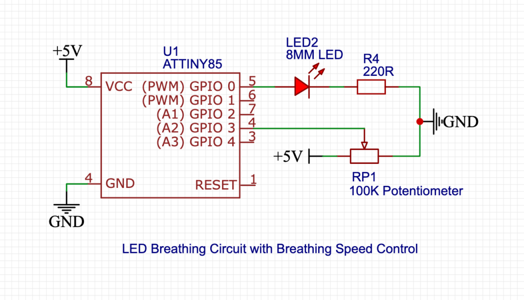
Circuit Diagram:
Here is the simplified Diagram of the Circuit. I designed it from EasyEDA Website.
Components Needed:
- Potentiometer (Any value from 10k to 250k, but 10k is preferred) – 1
- 220 Ohm Resistor – 1
- LED (Most commonly we use 5MM LED) – 1
- ATTiny85 – 1
- 5V Power Supply – 1
Tools Needed:
- Soldering Iron
- Solder Paste
- Pliers
- Cutter
- IC Holding Stand
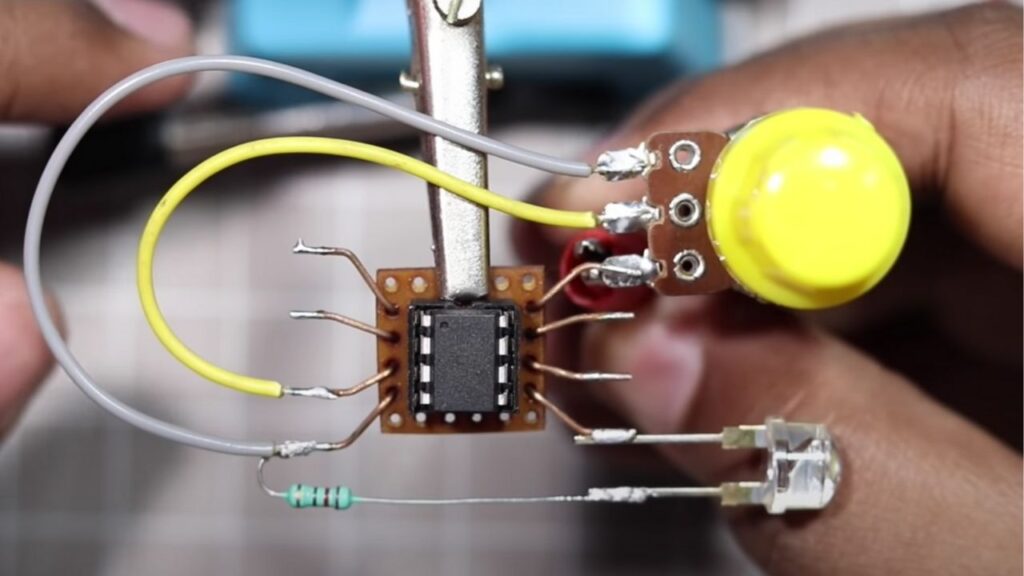
How to make it?
First, you will find a circle on the IC. This circle is used to indicate the Pin numbering of the IC. Now from their sequentially we count 1 to 8 Pinout. First, connect the LED positive with the IC Pin 5. Now connect the 220 Ohm Resistor with the negative of the LED. Now connect the other wire of the LED resistor with GND. In the same way, we will connect the Potentiometer with the AtTint85. and the circuit is complete.
Now upload the given code to the ATTiny Microcontroller at next you will be able to control the Duration of the LED Dimming.
LED Dimmer Code: Download
Making Video:
You can also watch the ATTiny85 Dimmer working Tutorial on our YouTube Channel.