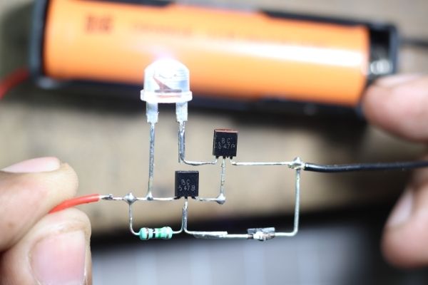
Here I made a simple Darkness sensor circuit using a Diode. Every Diode is mainly made up of P-type and N-type semiconductors.
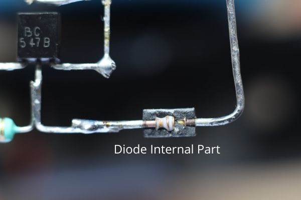
These semiconductors are secured in a Black casing. This is because light from outside will create obstacles to the Diode’s main works.
Here I removed the protective cover of the Diode and exposed it with direct light and I found there is a continuity going on to the circuit.
So, I used these specific characteristics to make a simple Darkness sensor.
Components:
- 1N4007 Diode
- BC547 Transistor
- 3.7v Li-ion Battery
- 1S Battery Holder
- 1M Resistor
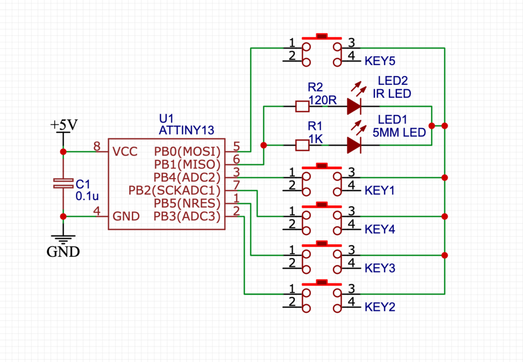
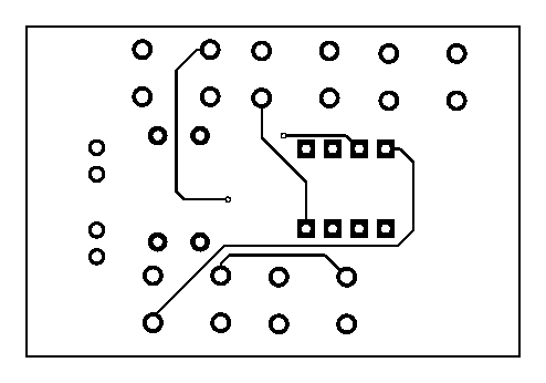
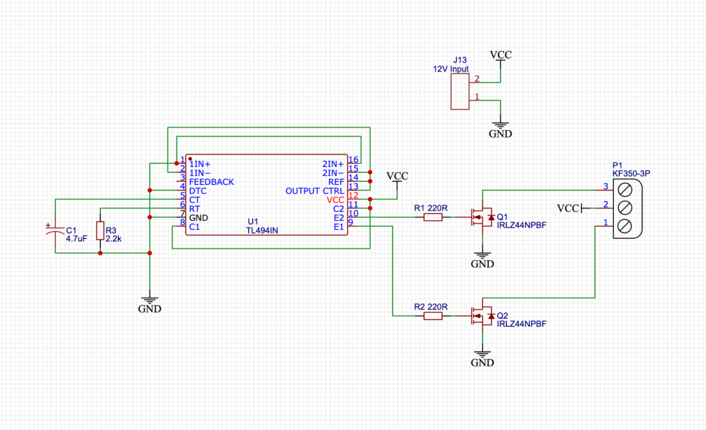
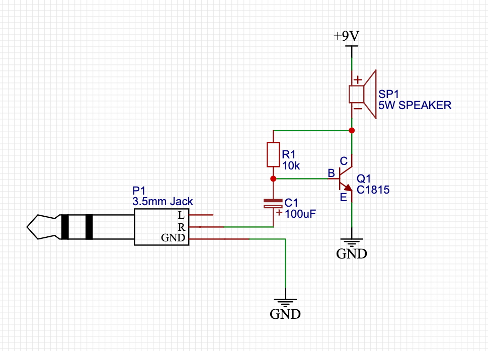
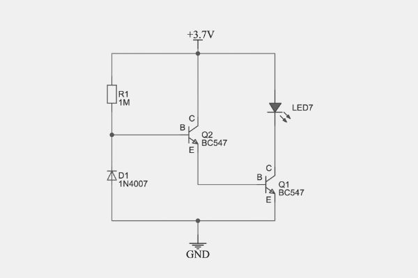
Circuit Schematics:
There is the simplified diagram made through EasyEDA.
How does the 4007 Simple Light Sensor work?
For sensing the light we generally use LDR also known as the light-dependent resistor. This is like a special type of resistor which can change its resistor value according to the light intensity. So it means that when the intensity of the light is high then the resistor value will be lower and when the intensity of the light is low then the resistor value will be infinite.
I have found nearly the same characteristics in a general-purpose diode. That’s why I just broke a diode shell and I find there are two conductors inside In it. They are P and N-type Semiconductors. The semiconductors and mainly doped with Silicon. So when we expose the internal material of the diode then the diode becomes conductive and able to flow current through it.
In the same principle, I made the circuit if you see the circuit diagram carefully you can see the diode is connected in Reverse Bias. So it means that it will not flow any current from Vcc to the ground without any modification.
So now the current flowing path is from Vcc to the Q2’s Base and now this signal is very small so it will not able to run the LED. That’s why we need to amplify the signal for using it. So, here it comes the Q2’s emitter pin is connected to Q1’s Base Pin so now this signal is amplified. This amplifier signal is now able to run or drive the LED.
This is a simple case. After when we modify the diode we can see when we give light to the diode then the LED will off
Here is why…
When we give light to the diode then it became conductive. so we all know that the current flows from the shortest path. so the current will flow from Vcc to the ground through the 1M resistor and the diode. No current will flow into the Q2’s base. So it will not activate the Q2 as well as the Q1 and the LED will not run.
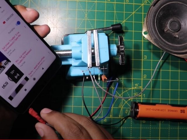
Watch Youtube Video:
Conclusion:
The main point is the diode is not that much light sensitive. So we will need a high intensity of light for running this circuit. Here I used a phone flash which has a high intensity of light. So this works just fine.