In this short descriptive article, I am going to discuss how to make an AC voltage detector circuit with intensity control. Here I am using some small components for making this. You can also get these components from old electronics circuit boards. We will need two NPN transistors and one PNP transistor. All connections are so simple that a beginner can also do that. I have also included schematics for better understanding.
How does the AC voltage detector circuit works?
This circuit is based upon simple transistors. We all know the transistor is used for switching and amplification purposes. here we are using the NPN transistors for signal amplification. The two NPN transistors are connected in the Darlington Pair configuration. This type of configuration is often used for signal amplification.
The 2nd NPN Transistor’s amplified signal grounds the PNP Transistor. So it activates the PNP Transistor. And this PNP Transistor Runs the LEDs.
From these two stages, we can get a signal on or off whether there is an AC connection or not. If there is on or off we will direct the signal to a PNP transistor so that this PNP transistor drives two LEDs.
This amplification was done through different stages. Like half stage and full stage. these are connected in such a way that first you will get the voltage first and another one. so when the stage is happening then the first led is getting voltage and the second it is not. so only one led is running. at the first stage, we can see e the PNP transistor is fully active so it runs all the current through the LEDs. So, In this state current flows both the LEDs. so that two LEDs light up.
I have told only two stages in this process for better understanding. but it is not like that it has few more than that. so when you were taking the wire near the AC line then the signal becomes stronger and two LEDs run. and when you take the wire far from the AC line then the two LEDs will off gradually.
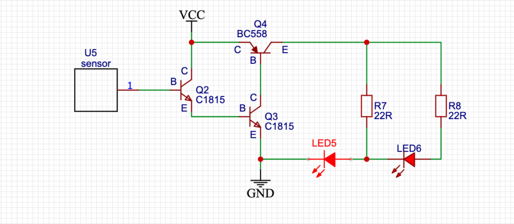
Schematics:
This schematic was designed in EasyEDA. I have also marked Emitter, Collector, Base for a better understanding of where to connect which components. Two 22R Resistors are mainly current limiting resistors. You can use any resistor value between 20R to 100R in place of a 22R resistor in case you have not found it.
The Q2 and Q3 are NPN Transistors. Here I used C1815 Transistors. Here any NPN Transistor will work just fine. The Q4 is the PNP Transistor. In this project, I used the BC558 PNP Transistor. You can also use any PNP Transistor as your wish.
The Q2 Transistor’s Base Pin is used for sensing the Pulses. so we have to connect an external Antena like thing with the transistor’s base. This thing is mainly a capacitor that mainly takes charges and after that, the transistor amplifies the signal.
For the LEDs you can use any. Like 3MM to 10MM any type of LED can be used in this circuit. I have 5MM LEDs laying around so I used 5MM Yellow LEDs.
For the Supply voltage I used 2S 18650 Li-ion Battery. Any voltage of 5V – 9V should be fine for this AC detector circuit with intensity control.
Components Used in this Project:
18650 Battery
18650 Battery Holder
LED
Resistor Set
Capacitor Set
3W LED
10MM LED
Transistor Set
Heat Shrink Tube
Tools Used:
Soldering Iron
Flux
Solder Stand
Soldering Paste
Wire Stripper
Cutter
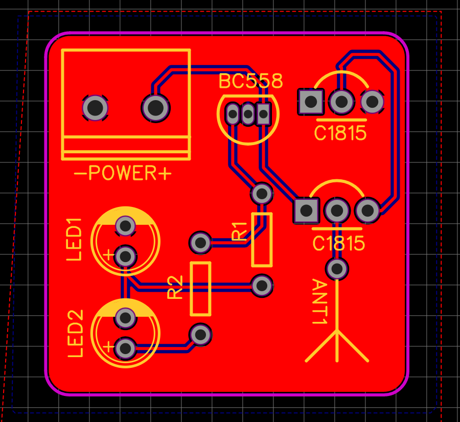
PCB File:
Here is the PCB File in case if you want to make a PCB of the Board.
PCB Top Layer
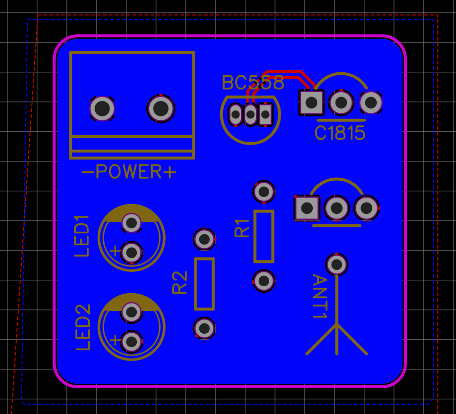
PCB Bottom Layer
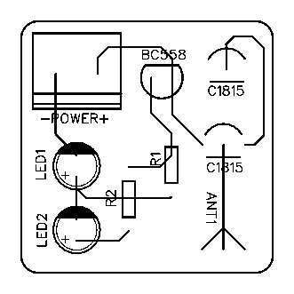
Here is the PCB files for Printout. Which you can print and use it for for Homemade PCB Making. You have to use PCB Aching Process for making the circuit in this way.
Top Part
Bottom Part
PCB Gerber:
Here is the Gerber file which you can send to any PCB Manufacturing company for making a professional PCB for the project.
Here is the video that explains all the necessary connections for making this simple circuit. Make sure you double-check all the connections before making the circuit. Otherwise, you may fry the transistors.
Conclusion:
This project needs a very small handful of components. So, you should definitely try this at your home. Electronics are easy and fun. But be careful while working with high voltages. You can get all the components from your local shop or from old electronics motherboards, DVD players, and much more. If you like this type of small circuit you may definitely subscribe to Creative Creator for more amazing content like this.
LED Dimmer circuit is a simple circuit. It helps us to Increase and decrease the brightness of the LED. Previously it was common that we would use some type of Controllers (For simple PWM signal Generation we use 555 Timer IC) to make the PWM signal and from the PWM signal we will we would drive the MOSFET. This is a very old process of dimming the LED.
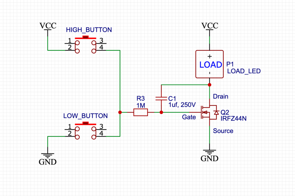
Schematics:
Here is the simple schematics which I designed in EasyEDA.
LED Dimmer circuit with MOSFET
How does the LED Dimmer with Capacitor work?
We can use MOSFET’s basic characteristics for making the circuit. We all know that the MOSFET is a special kind of Transistor that is more efficient and more powerful than General BJT Transistors. Every MOSFET has an inbuilt capacitor in it. This capacitor is very small. So, we can’t vary the voltage using the capacitor inside of the MOSFET. So, I used an external AC capacitor. Here the polarity is changing so we can’t use a DC capacitor here because there will be reverse voltage in the DC capacitor.
And you know what DC capacitors don’t like reverse voltage. So, In this current stage, we can’t use a DC capacitor. So, we have to use an AC capacitor only where the polarity is changing.
If you see the circuit carefully here you will find that there is a gate resistor for charging the capacitors slowly. So, It will charge and discharge the capacitor slowly. Here we are using some small buttons for charging and discharging purposes. So, the upper button is directly connected to the Vcc.
The upper button directly charges the capacitor and it activates its drain to the source path gradually. And also you can see there is a push-button corrected to the GND. It is mainly a discharging stage. So, when you press this button then the capacitor discharges gradually by the 1M resistor.
This sequential charging and discharging makes possible us to varying the voltage.
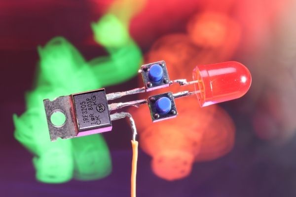
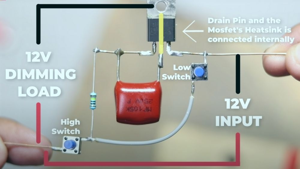
Connection with Components:
Here is the simple components view for the circuit.
LED Dimmer circuit with MOSFET
Limitation:
In schematics you can see there are two buttons connected in series one is connected to the ground and the other is connected to the Vcc. So, The main and the most annoying limitation is that in the circuit you can’t connect both switches at the same time. You have to press the switches one at a time. It is the only limitation I found about this circuit.
In future I am trying to overcome this problem by new circuit. For now this is the simplest LED dimmer circuit with only capacitor and some buttons.
This the demonstration video from creative Creator. Watch it and you will understand how to wire everything.
Conclusion:
So, all in all, this is a pretty simple circuit for beginners who want to start their electronics journey. You know what this hobby is not that expensive. you can harvest many electronics from old, not working boards. Like me, I have used all inverter board MOSFET in this video. And for the capacitor, you can use any high-value capacitor higher than 1UF so that you can get high dimming stages. and for the resistor, the rule also applies the same. You can use any high-value resistor greater than 1M is also fine for this project. And don’t forget to subscribe to Creative Creator for more amazing content like this.
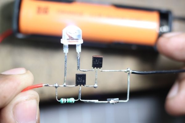
Here I made a simple Darkness sensor circuit using a Diode. Every Diode is mainly made up of P-type and N-type semiconductors.
These semiconductors are secured in a Black casing. This is because light from outside will create obstacles to the Diode’s main works.
Here I removed the protective cover of the Diode and exposed it with direct light and I found there is a continuity going on to the circuit.
So, I used these specific characteristics to make a simple Darkness sensor.
Components:
1N4007 Diode
BC547 Transistor
3.7v Li-ion Battery
1S Battery Holder
1M Resistor
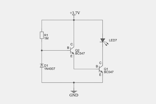
Circuit Schematics:
There is the simplified diagram made through EasyEDA.
How does the 4007 Simple Light Sensor work?
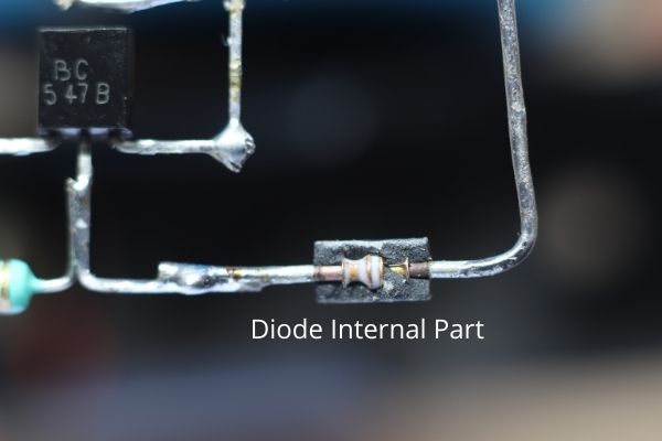
For sensing the light we generally use LDR also known as the light-dependent resistor. This is like a special type of resistor which can change its resistor value according to the light intensity. So it means that when the intensity of the light is high then the resistor value will be lower and when the intensity of the light is low then the resistor value will be infinite.
I have found nearly the same characteristics in a general-purpose diode. That’s why I just broke a diode shell and I find there are two conductors inside In it. They are P and N-type Semiconductors. The semiconductors and mainly doped with Silicon. So when we expose the internal material of the diode then the diode becomes conductive and able to flow current through it.
In the same principle, I made the circuit if you see the circuit diagram carefully you can see the diode is connected in Reverse Bias. So it means that it will not flow any current from Vcc to the ground without any modification.
So now the current flowing path is from Vcc to the Q2’s Base and now this signal is very small so it will not able to run the LED. That’s why we need to amplify the signal for using it. So, here it comes the Q2’s emitter pin is connected to Q1’s Base Pin so now this signal is amplified. This amplifier signal is now able to run or drive the LED.
This is a simple case. After when we modify the diode we can see when we give light to the diode then the LED will off
Here is why…
When we give light to the diode then it became conductive. so we all know that the current flows from the shortest path. so the current will flow from Vcc to the ground through the 1M resistor and the diode. No current will flow into the Q2’s base. So it will not activate the Q2 as well as the Q1 and the LED will not run.
The main point is the diode is not that much light sensitive. So we will need a high intensity of light for running this circuit. Here I used a phone flash which has a high intensity of light. So this works just fine.
Today in this article we are going to discuss how to make an IR remote controller with an Attiny microcontroller. We can use any microcontroller for this project but for low being low complexity and making the circuit as small as possible we are using an AtTiny13a Microcontroller. But you can also use any popular microcontroller board like Arduino UNO, Arduino NANO as your wish. Both will work just fine.
Components for the Circuit:
Push Button – 5
ATTiny 13 IC – 1
100R Resistor – 1
1k Resistor – 1
0.1uF Capacitor – 1
2 Pin Screw Terminal Block – 1
3.7v Battery – 1
PCB – 1
5MM LED – 2
IR LED – 1
Tools Required:
Soldering Iron 60W Recommended
Soldering Stand
PCB Stand
Soldering Iron Fine Tip.
Tip Cleaner
Pliers
Jigsaw.
Flux
PCB Holder.
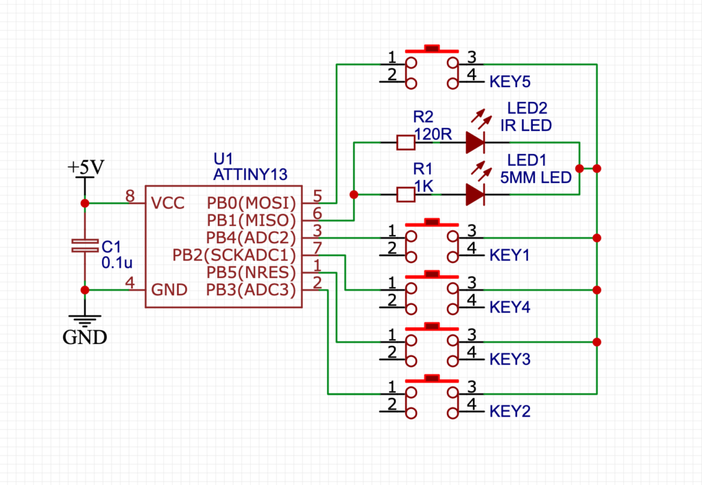
Circuit Diagram:
I designed the Schematics in online through Easyeda Website.
How Does the Microcontroller-based remote control works?
Every Remote has an integrated chip inside it. When any company makes Any smart device then they just give a hex code to the program IC. So, first, we have to identify the hex code. And it is very simple by using the given code in the Arduino example code. Then we will map the values to the ATtiny Micro-controller Pins. In this simple way, we can map any necessary switch and make the smallest remote.
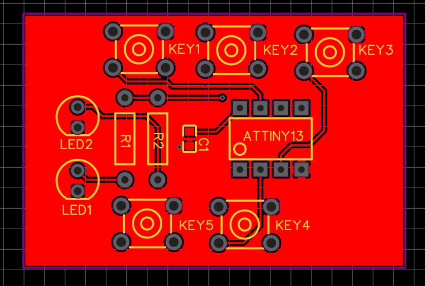
PCB Making:
I made the schematics. Then I ordered it from PCB from JLCPCB. Their work is professional. PCB looks Promising and can ship to your doorstep within a week. I have to say their customer service is superior. So, I prefer JLCPCB from Other PCB Manufacturers. You can also order from them.
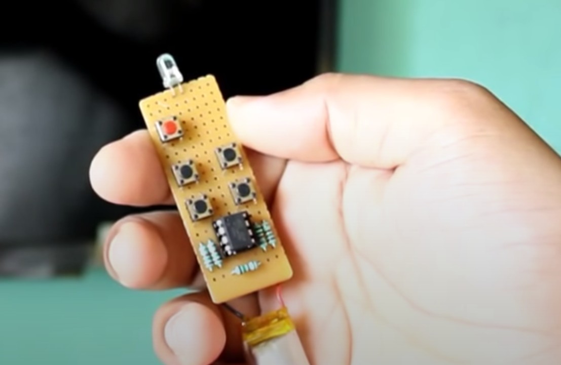
Top Silk Layer Preview:
Here is the Top Silk Layer preview of the PCB. 5 Switches are used in this Circuit for different functions.
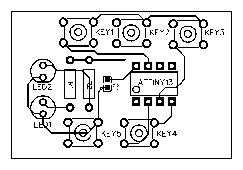
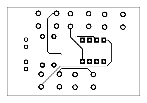
PCB Layout:
Here is the Top Layer and the Bottom Layer of the PCB. You can use this pictures to make the PCB in home through your Printer. And with some PCB Aching process you can make the PCB at home.
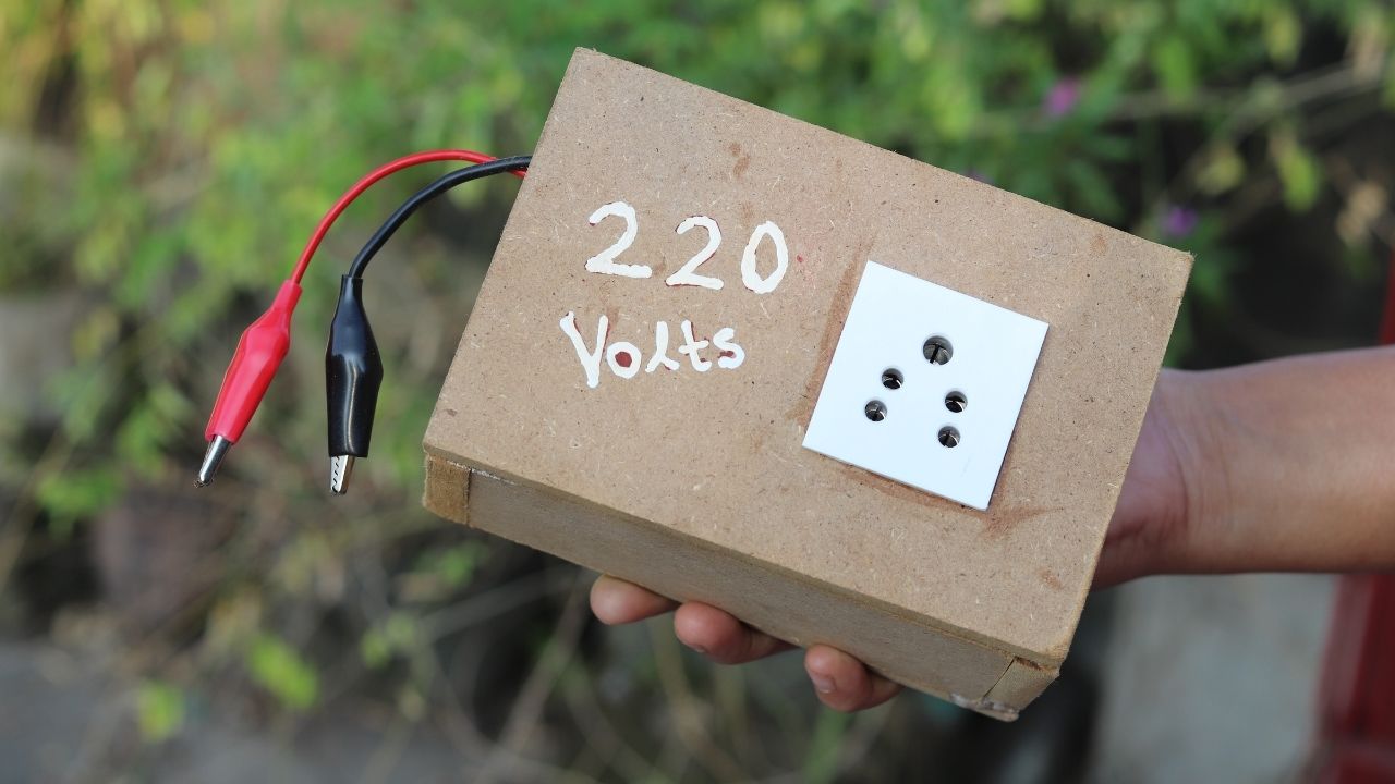
Today in this article we are going to make a 100W Inverter circuit with TL494 PWM IC. The main function of the IC is to create variable PWM Pulses for different applications. Now for making the Inverter we have to make a 50Hz signal ( By calculating PWM Pulses). We will use a couple of other complimentary components for making the Inverter possible. The components are Some Resistors and a capacitor.
If we check the IC Datasheet then we will find some Important equations to calculate the important parameters of the IC. Sometimes it is also not possible to get the exact value of the components. Then our motive will be to find the components which have the nearest value.
Components for the Circuit:
TL494 IC – 1
IRFZ44N MOSFET – 2
220R Resistor – 2
2.2k Resistor – 1
4.7uF Capacitor – 1
2 Pin Screw Terminal Block – 1
3 Pin Screw Terminal Block – 1
12v Battery Connector – 2
12v Battery – 1
MDF Sheet (8MM) – 1
10MM Wood Screws – 20
5 Pin Socket – 1
220v to 12v-0-12v Transformer – 1
Tools Required:
60W Soldering Iron
Soldering Iron Fine Tip.
Soldering Iron Tip Cleaner
Pliers
Jigsaw.
Drill Machine.
Different Drill Bits.
Glue Gun
Flux
PCB Holder.
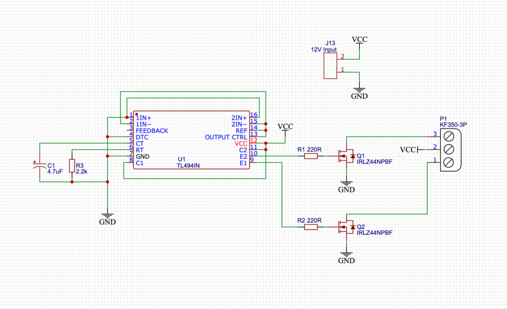
Circuit Diagram:
The P1 terminal block is used for sending the 12V DC Power and The J13 terminal is for giving the 12V Input to the circuit. For the Mosfets, you can use an N-channel MOSFET as your wish. I had the IRFZ44n Mosfet lying around so I used that. You can also use IRF3205 as well.
How does the TL494 Inverter work?
This is the simplified diagram for the 100W Inverter Project. R1 and R2 are the Gate resistors for the MOSFETs. this protects the MOSFET from over-voltage damage. The voltage that is needed to operate the MOSFET will be provided by the Gate resistor. So, The gate resistor is a very important component.
Now for generating the 50Hz signal we only need 2 basic components. One Capacitor couple with a resistor. And the P1 Terminal block is for sending the squire wave pulses to the Transformer Primary coil. Now from the Transformer secondary coil, we will get the 220V Output.
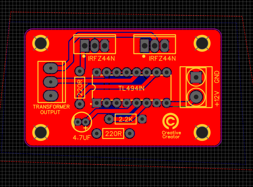
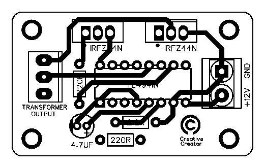
PCB Making:
I made the schematics and the PCB. Then I ordered it from PCB manufacturer JLCPCB. They are professional at their work. PCB looks Promising and can ship to your doorstep within a week. I have to say their customer service is superior. So, I prefer JLCPCB from Other PCB Manufacturers. You can also order PCB from JLCPCB with the following Gerber file.
How to Make a Simple 5W Audio Amplifier Circuit with C1815 NPN Transistor?
C1815 is a BJT Type NPN Transistor. Generally, the NPN Transistors are mainly used for Switching, Amplification. This example circuit is a basic example of Transistor Amplification. Not only C1815 but also you can also use any NPN Transistor you have lying around. The Amplifier output power may differ according to the Transistor rating. Here we will get a maximum of 5W output from the amplifier. For a general user, 5W Speaker is more then enough else if he is a heavy music lover.
Amplifier Working:
Every audio signal is more likely an oscillation. The amplitude of this oscillated signal is low when it is generated. Mainly we find this type of signal in Mobile Phones, laptops, and other media devices outputs. More likely this signal is suitable for driving small earphones headphones. Here we will increase the amplitude of the media signal and then connect it with a speaker for listening to the loud sound.
Components Needed:
C1815 NPN Transistor – 1
10k Resistor – 1
100uF Capacitor – 1
Small 5W Speaker – 1
3.5mm Audio Jack – 1
9V Battery – 1
Tools Used:
Soldering Iron
Soldering Paste
Nose Pliers
Wire Cutter
Breadboard
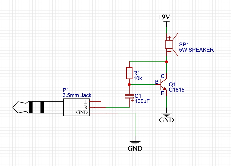
Circuit Diagram:
I designed the circuit schematics diagram on free online software EasyEDA.
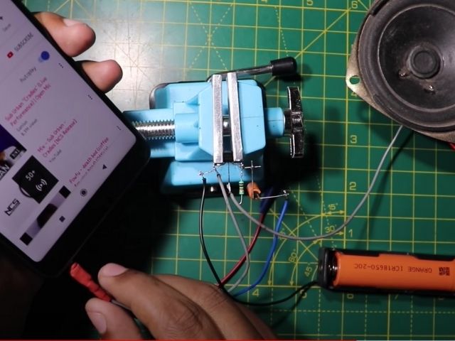
How to Make it?
First, gather all the components as I mentioned earlier. Now attach all the components step by step. First, connect the Transistor’s collector and base with a 10k Resistor. Now take the 100uF capacitor and connect it’s -ve with. For the audio transmission, we will need a jack. Here I am using an old 3.5MM Jack from an old Headphone. You can also get this jack from online in a couple of bucks.
The circuit is ready to give power to the transistor. It is recommended to use any voltage between 5 to 12V. In the next run, a song from your media device and you are good to go. Now you can enjoy your shooting pleasant music with high volume.
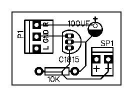
PCB Layout:
PCB Fabrication File:
Here is the Gerber file for the PCB if you want to replicate the same thing.
This is the Video from Creative Creator that will help you to replicate the amplifier. Make Sure you Subscribe to our channel.
Conclusion:
Lastly, I would say this is an easy circuit for electronics enthusiasts for making something new. If you are a beginner then you should definitely try making this and maybe you can make your first Boom Box with it. This is a Basic BJT NPN amplifier so it means that you can also use a more powerful amplifier with a more powerful transistor.
How to make a Variable Dimmer Circuit with ATTiny85 Microcontroller?
Today in this article we are going to make a variable LED Dimmer circuit with a very small microcontroller that is ATTiny85. I will also add the needed codes below. For now, let’s try to understand basically the variable LED Dimmer Circuit Works? and what are the basic components you will need.
ATTiny85 Working:
ATTiny85 is an 8 Pin single chip Microcontroller. It has 2 PWM Pins and 3 Digital Pins. You can configure the IC with Arduino IDE as your wish. Generally, all Arduino boards need an external crystal oscillator for running. But it has an internal 8MHz Oscillator inside in it.
So, the ATTiny85 makes sense when you are dealing with Low Input and Output counts. Like a Hall Effect Sensor or an IR Sensor for input and an LED for the Output Indication. In these cases, we use ATTiny85 Microcontroller.
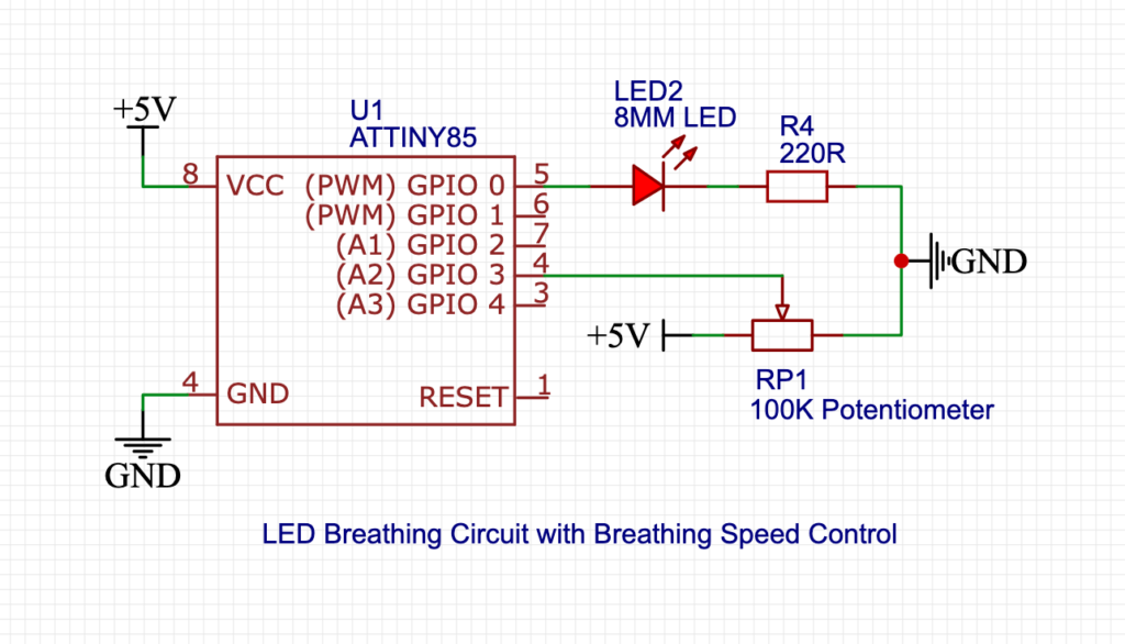
Circuit Diagram:
Here is the simplified Diagram of the Circuit. I designed it from EasyEDA Website.
Components Needed:
Potentiometer (Any value from 10k to 250k, but 10k is preferred) – 1
220 Ohm Resistor – 1
LED (Most commonly we use 5MM LED) – 1
ATTiny85 – 1
5V Power Supply – 1
Tools Needed:
Soldering Iron
Solder Paste
Pliers
Cutter
IC Holding Stand
How to make it?
First, you will find a circle on the IC. This circle is used to indicate the Pin numbering of the IC. Now from their sequentially we count 1 to 8 Pinout. First, connect the LED positive with the IC Pin 5. Now connect the 220 Ohm Resistor with the negative of the LED. Now connect the other wire of the LED resistor with GND. In the same way, we will connect the Potentiometer with the AtTint85. and the circuit is complete.
Now upload the given code to the ATTiny Microcontroller at next you will be able to control the Duration of the LED Dimming.
LED Dimmer Code: Download
Making Video:
You can also watch the ATTiny85 Dimmer working Tutorial on our YouTube Channel.