
Introduction:
LED Dimmer circuit is a simple circuit. It helps us to Increase and decrease the brightness of the LED. Previously it was common that we would use some type of Controllers (For simple PWM signal Generation we use 555 Timer IC) to make the PWM signal and from the PWM signal we will we would drive the MOSFET. This is a very old process of dimming the LED.
Schematics:
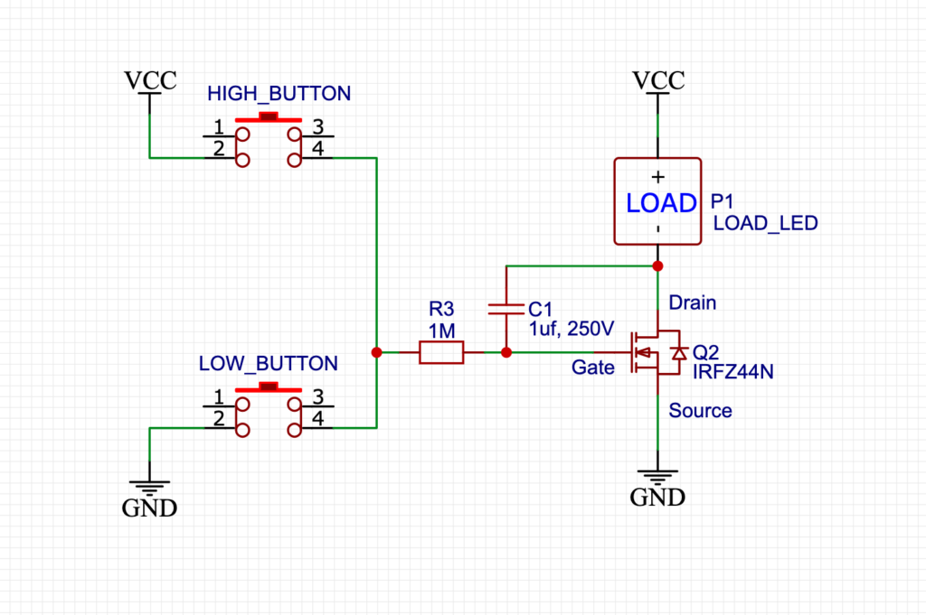
Here is the simple schematics which I designed in EasyEDA.
How does the LED Dimmer with Capacitor work?
We can use MOSFET’s basic characteristics for making the circuit. We all know that the MOSFET is a special kind of Transistor that is more efficient and more powerful than General BJT Transistors. Every MOSFET has an inbuilt capacitor in it. This capacitor is very small. So, we can’t vary the voltage using the capacitor inside of the MOSFET. So, I used an external AC capacitor. Here the polarity is changing so we can’t use a DC capacitor here because there will be reverse voltage in the DC capacitor.
And you know what DC capacitors don’t like reverse voltage. So, In this current stage, we can’t use a DC capacitor. So, we have to use an AC capacitor only where the polarity is changing.
If you see the circuit carefully here you will find that there is a gate resistor for charging the capacitors slowly. So, It will charge and discharge the capacitor slowly. Here we are using some small buttons for charging and discharging purposes. So, the upper button is directly connected to the Vcc.
The upper button directly charges the capacitor and it activates its drain to the source path gradually. And also you can see there is a push-button corrected to the GND. It is mainly a discharging stage. So, when you press this button then the capacitor discharges gradually by the 1M resistor.
This sequential charging and discharging makes possible us to varying the voltage.
Connection with Components:
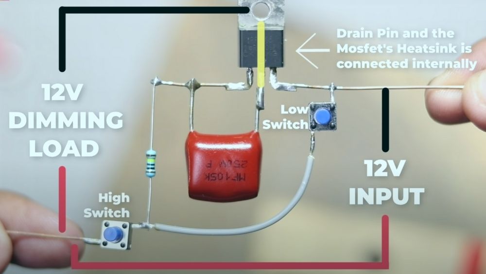
Here is the simple components view for the circuit.
Limitation:
In schematics you can see there are two buttons connected in series one is connected to the ground and the other is connected to the Vcc. So, The main and the most annoying limitation is that in the circuit you can’t connect both switches at the same time. You have to press the switches one at a time. It is the only limitation I found about this circuit.
In future I am trying to overcome this problem by new circuit. For now this is the simplest LED dimmer circuit with only capacitor and some buttons.
Components used in the video:
Amazon US:
- IRF3205: https://amzn.to/3nCSdrK
- 105k, 250V AC Capacitor: https://amzn.to/2KFmSpn
- Push Button: https://amzn.to/3p4TVCp
- 8MM LED: https://amzn.to/3p8oGGH
- 5MM LED Set: https://amzn.to/2WqJ7Cr
- 30W LED: https://amzn.to/2LKpnY9
- 100W LED: https://amzn.to/37tGrdh
- Wire Stripper: https://amzn.to/38jonlh
- 18650 Battery: https://amzn.to/3dITQ2O
- 18650 Battery Holder: https://amzn.to/3ofXBll
- LED: https://amzn.to/3dH48QO
- 555 Timer: https://amzn.to/3jeOwVV
- Resistor Set: https://amzn.to/2HfW5Ph
- Soldering Iron: https://amzn.to/3dJIVpm
- Capacitor Set: https://amzn.to/2Tc2DRg
- Female Header: https://amzn.to/2TdGT7u
Amazon India:
- IRF3205: https://amzn.to/34pTsTz
- 105k, 250V AC Capacitor: https://amzn.to/2LGcjTC
- Push Button: https://amzn.to/3p2oWXA
- 8MM LED: https://amzn.to/3h3ahZA
- 5MM LED Set: https://amzn.to/34ptS0O
- 30W LED: https://amzn.to/3mAqeYa
- 100W LED: https://amzn.to/37v66Cm
- Wire Stripper: https://amzn.to/37tuy7o
- 18650 Battery: https://amzn.to/3m1oqHQ
- 18650 Battery Holder: https://amzn.to/3o80bJR
- LED: https://amzn.to/35db7ND
- 555 Timer: https://amzn.to/37n1AGp
- Resistor Set: https://amzn.to/31pfKmD
- Soldering Iron: https://amzn.to/37oeST2
- Capacitor Set: https://amzn.to/31o16Mm
- Female Header: https://amzn.to/37kOs4M
Watch Video:
This the demonstration video from creative Creator. Watch it and you will understand how to wire everything.
Conclusion:
So, all in all, this is a pretty simple circuit for beginners who want to start their electronics journey. You know what this hobby is not that expensive. you can harvest many electronics from old, not working boards. Like me, I have used all inverter board MOSFET in this video. And for the capacitor, you can use any high-value capacitor higher than 1UF so that you can get high dimming stages. and for the resistor, the rule also applies the same. You can use any high-value resistor greater than 1M is also fine for this project. And don’t forget to subscribe to Creative Creator for more amazing content like this.
Have a great day!